A set of interdependent thermodynamic values consistent with the Fe-Si phase diagram based on a critical assessment of all the published phase diagram and thermodynamic data has recently been submitted by Chart 1. Al-Mg-Si PHASE DIAGRAM The Al-Mg-Si phase diagram can be used for the analysis of many wrought alloys of 6XXX series and casting alloys of the 3560 type provided the concentration of iron impurity is low Table 21.

Figure 8 From High Temperature 550 700 C Chlorosilane Interactions With Iron Semantic Scholar
Binary silicon compounds can be grouped into several classes.

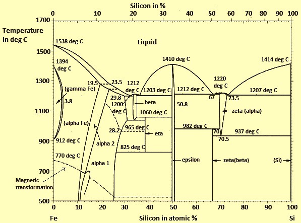
Iron silicon phase diagram. At 5 silicon the critical iron content is. Within a small intermediate region at -70 a Si FeSi2h and Mn11 Si19 appear at the liquidus surface. Hansens German monograph was followed by a revised English edition in 1958 with K.
EUR 9657IEN Commission of the European Communities 130p1985. Technically the term silicide is reserved for any compounds containing silicon bonded to a more electropositive element. It is relatively unreactive.
The liquidus surface is divided at 50 a Si by the continuous ridge ofMnFeSi. It is a relatively simple binary diagram where there is very little solubility at room temperature for Si in Al and for Al in Si. Manganese-iron-silicon The ternary system manganese-iron-siliconis shown in figure 9 and 10.
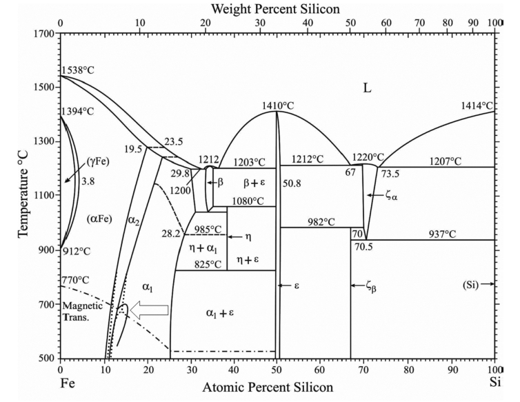
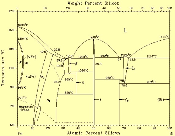
Iron-silicon phase diagram shows the phases which are to be expected at equilibrium for different combinations of Si content and temperature. Silicon is a chemical element with the symbol Si and atomic number 14. It is a hard brittle crystalline solid with a blue-grey metallic lustre and is a tetravalent metalloid and semiconductorIt is a member of group 14 in the periodic table.
60 Zeilen Experimental iron-silicon phase diagram Binary compounds of silicon are binary chemical compounds containing silicon and one other chemical element. A map of the temperature at which different phase changes occur on very slow heating and cooling in relation to Carbon is called Iron- Carbon Diagram. Solid α Liquidus line separates liquid region from liquid solid region above this line there lies only liquid solution.
318 illustrates this diagram and photomicrographs of alloys at room temperature. Raghavan The Cr-Fe-Si SystemPhase Diagrams of Ternary Iron Alloys. Part 1 ASM International Metals Park OH 3142 1987.
Phase Diagrams for Binary and Ternary Alloys of Fe-Cr and Ni with C and with Si Ref. In the Si-richpartthe two phases MnFeSi and Si are the dominating primary phases. 8 shows a section of the liquidus projection of the Al-rich corner of the Al-Si-Fe ternary phase diagram with additional construct lines that highlights the existence of a critical iron content.
101007s11669-010-9653-4 1547-7037 ÓASM International Fe-Ni-Si Iron-Nickel-Silicon V. Thus the terminal solid solutions are nearly pure Al and Si under equilibrium conditions. The lowest melting point ofthis part is.
Al-Si diagram is a eutectic diagram where solid solubility at least of aluminium in silicon is negligible and maximum solubility of silicon in aluminium at eutectic temperature is 165. This phase diagram is also necessary for the analysis of more complex systems. This phase diagram can be used for the analysis of the phase composition of an 8001 alloy Table 71 that contains only nickel and iron as the alloying elements.
Alloys of Al-Si are very important casting alloys mainly because of high. Silicon ferrosilicon and other silicon alloys are produced by reducing quartz with coal and iron or other ores at very high temperatures 2000C in electric arc furnaces. There is no need to point out the importance of assessed phase diagrams to metallurgists or even anyone concerned with the technology and applica tion of metals and alloys.
Because of its high chemical affinity for oxygen it was not. The information contained therein is fundamental to considerations concerning the chemical physical and mechanical properties of alloys. As the silicon content of the alloy increases the amount of iron that can be tolerated before the E-phase starts to form prior to the Al-Si eutectic increases.
The Al-Si Phase Diagram The binary Al-Si phase diagram was initially studied by Fraenkel of Germany in 1908. Iron- Carbon diagram shows - the type of alloys formed under very slow cooling proper heat-treatment temperature and how the properties of steels and cast irons. The phase diagram of the Fe-Si binary system is at Fig 1.
The eutectic composition is 127 silicon. Phase Diagram Three phase region can be identified on the phase diagram. Iron-silicon phase diagram.
The currently accepted diagram Figure 1 is. Solidus line separates solid region from liquid solid region below this line only solid solution is present. Raghavan The review of this system by 1988Ray presented a an ordered phase FeNi3 L12 AuCu3-type cubic forms tentative liquidus projection partial isothermal sections at congruently from c.
Carbon is above it. And germanium tin and lead are below it. Solid liquid α L 3.
Simultaneously Schürmann and Hensgen 2 re-determined the melting and solid state equilibria in the region Fe-FeSi of samples prepared from Rein-Eisen or electrolyte iron and Si. Microstructures observed on eutectic and eutectoid phase diagram for different composition values are explained. This diagram is also the basic diagram for casting alloys of the 5120 type that are considered in Chapter 4.
Phase Diagram Evaluations JPEDAV 2010 31184185 DOI. 385 Some silicon gas or fume is produced in the process and reaches the top of the furnace with other combustion gases where it becomes oxidised to silica by the air and then condenses as submicroscopic particles. In the Fe-Si system Massalski2 the 1000 800 600 and 450 C for Ni-rich alloys two computed Fe-based face-centered cubic phase.

Fe Si Phase Diagram Of 0 01 0 02 Weight Carbon Steel Download Scientific Diagram
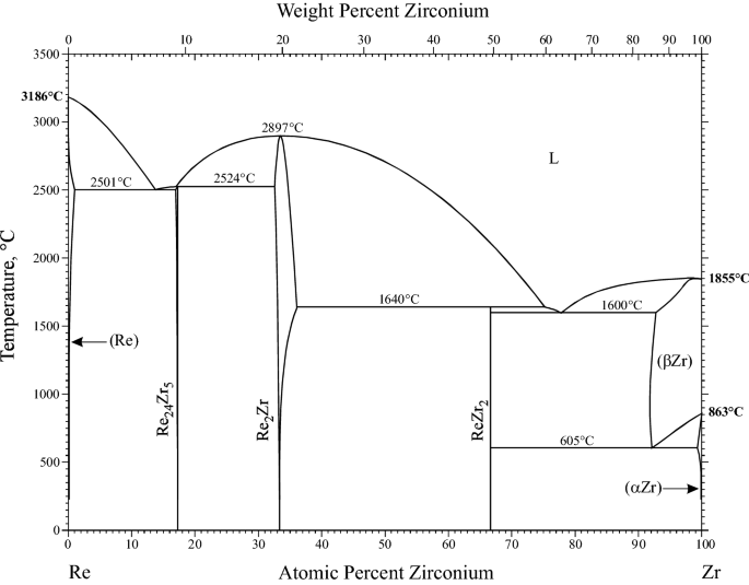
Supplemental Literature Review Of Binary Phase Diagrams Al Pt As U C Li C Mg Cd Nd Co Ta Fe Re Ga Y La Ni O V P Si And Re Zr Springerlink
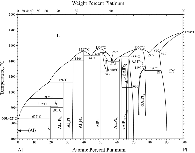
Supplemental Literature Review Of Binary Phase Diagrams Al Pt As U C Li C Mg Cd Nd Co Ta Fe Re Ga Y La Ni O V P Si And Re Zr Springerlink

Ti Si Binary Phase Diagram Download Scientific Diagram

Fe Si Phase Diagram 16 And Alloy Quench Temperatures Download Scientific Diagram
Fig 1 Bulk Phase Diagram Of Iron Silicon Compounds After Hansen Ref 4 Diagram Iron Crystalline Structure
The Fe Si Phase Diagram From Electrical Steel To The Planet Mercury Center For Molecular Modeling

Binary Compounds Of Silicon Wikipedia

Fe Si Phase Diagram 16 And Alloy Quench Temperatures Download Scientific Diagram
Silicon In Steels Ispatguru

Characterization Of The Evaluation Of The Solid Solubility Of Si In Sintered Fe Si Alloys Using Dsc Technique Sciencedirect
Ferro Silicon Ispatguru

The Iron Aluminum Phase Diagram Download Scientific Diagram
Some Phase Diagrams